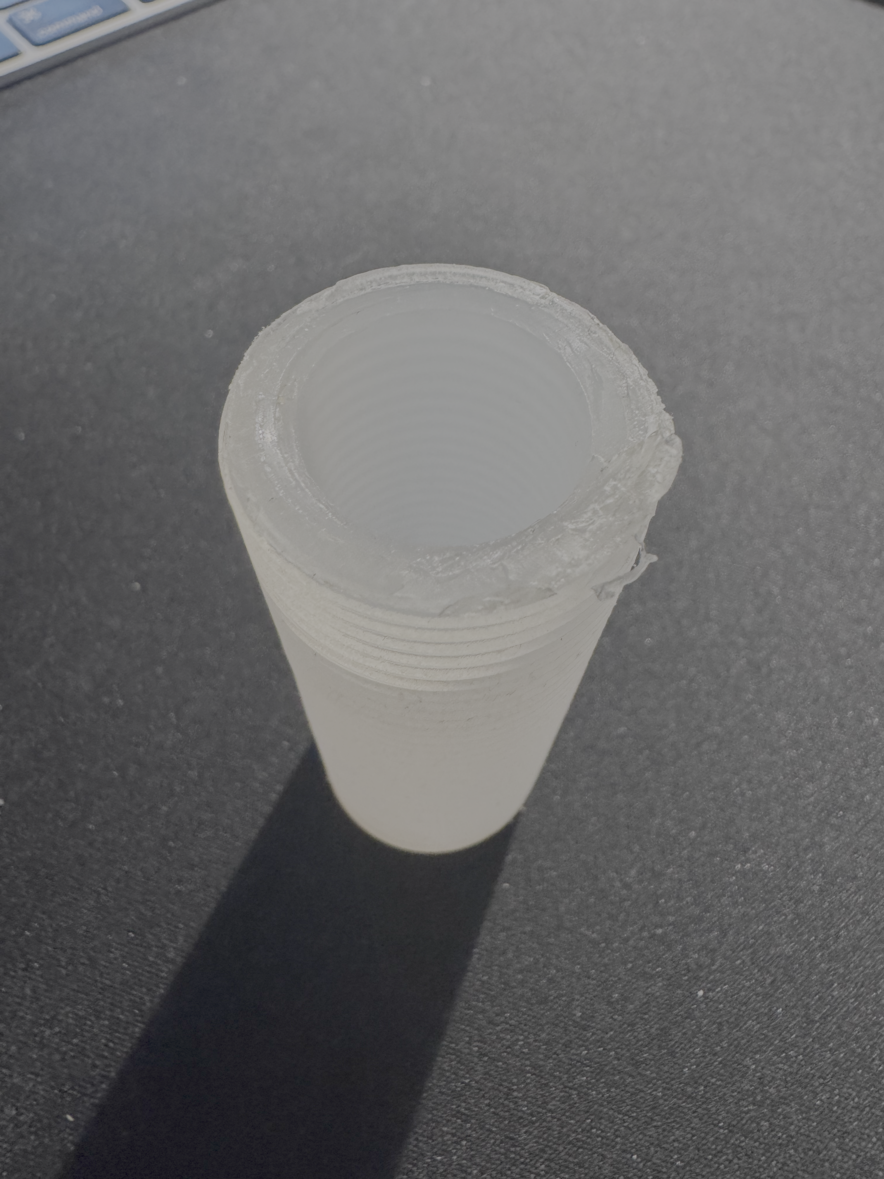
A few weeks ago a small plastic part inside our kitchen soap dispenser cracked. The dispenser is a Grohe Cosmopolitan — nice piece of kitchen hardware, built into the countertop, the kind of thing you stop noticing until it stops working. Inside that brushed steel housing is a humble plastic tube — a column with threads on the outside and threads on the inside — that holds the pump and the soap bottle together.
That tube had snapped at the threads. The official Grohe replacement: ~€80. For a piece of plastic.
I refused.
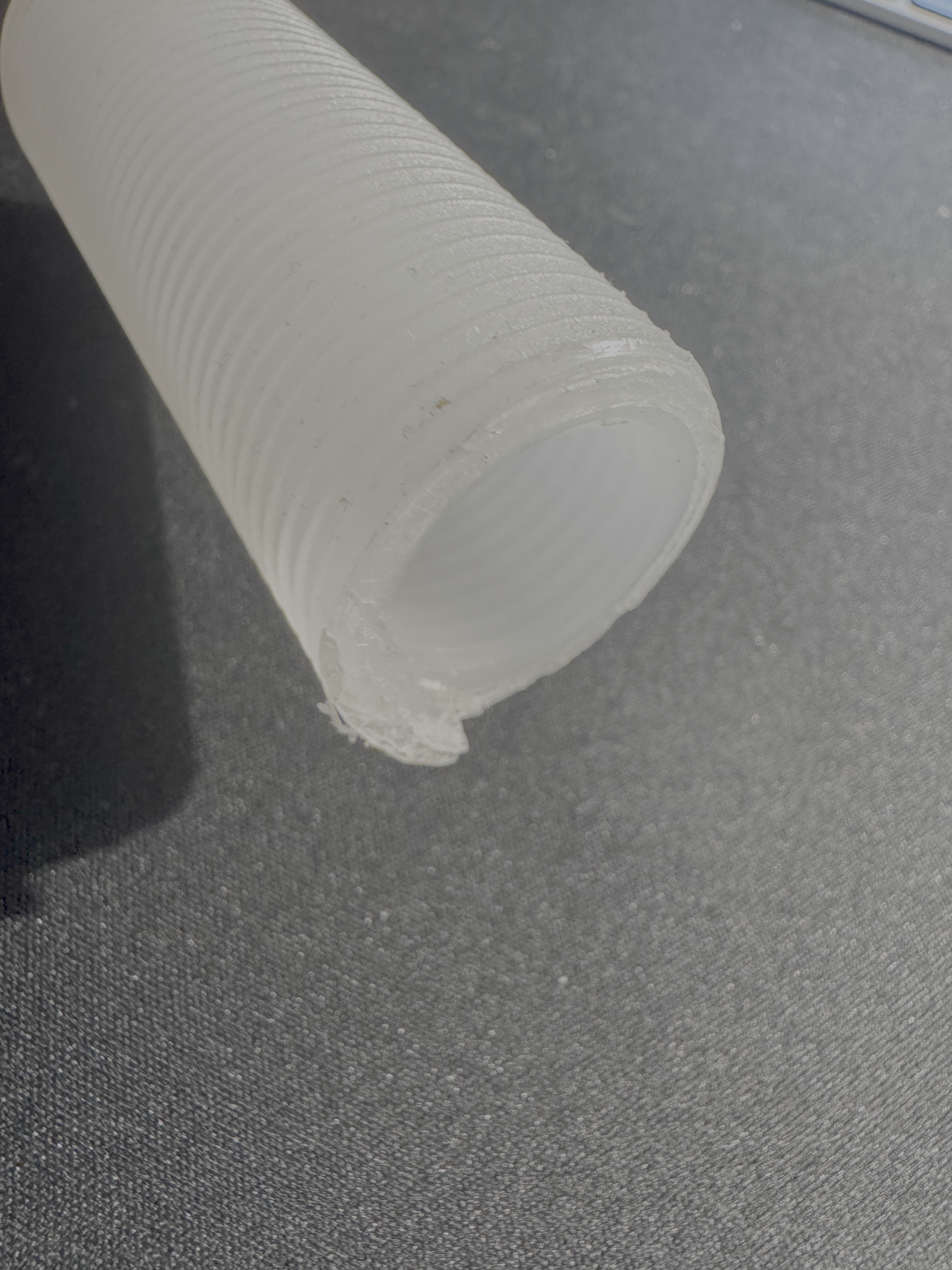
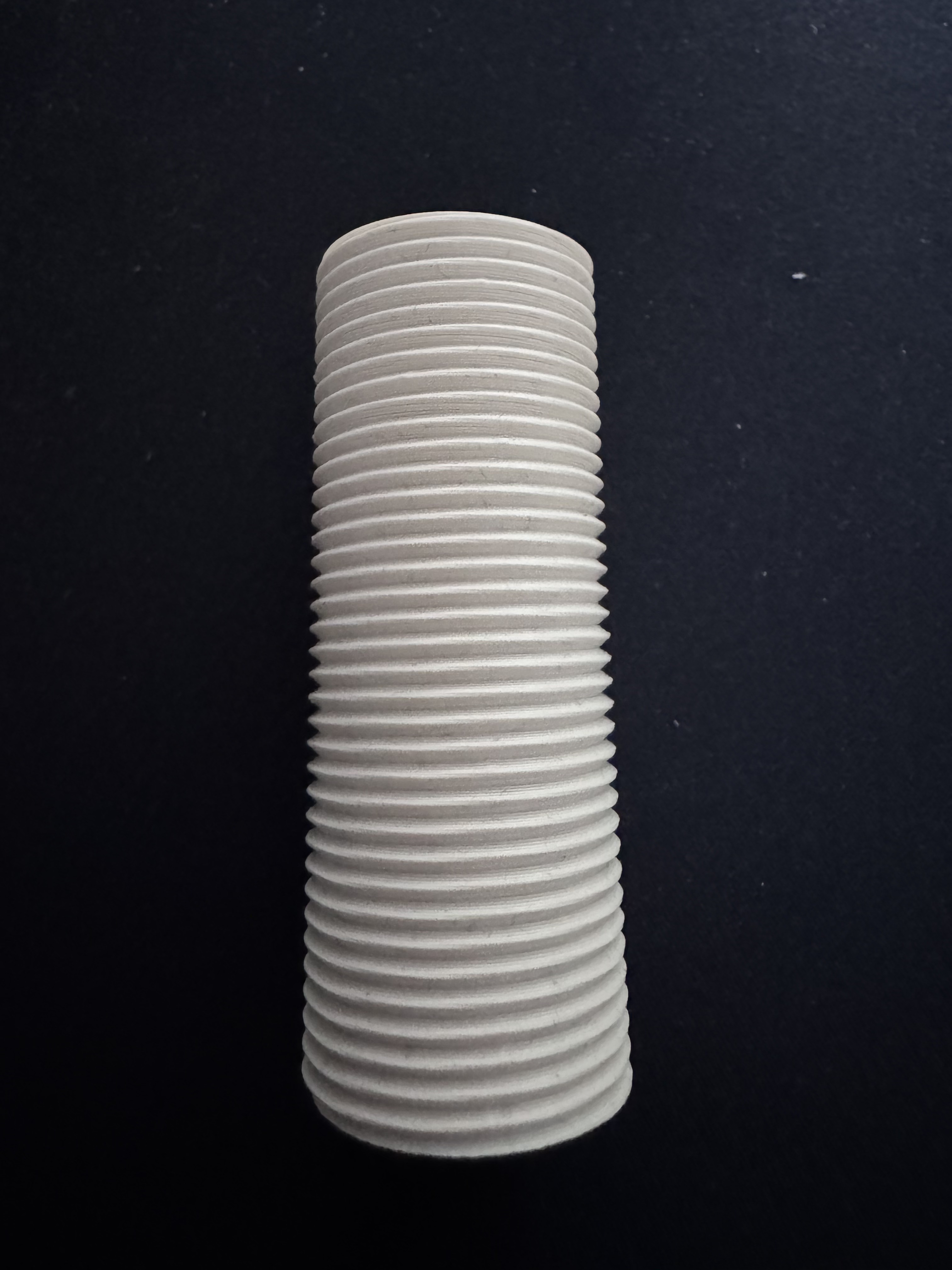
The patient. Threads outside, threads inside, ~73 mm tall. The top end (where the bottle threads in) had cracked off.
I have a 3D printer (a humble Bambu Lab A1), a roll of PLA, and the only thing standing between me and a working dispenser was a CAD model. I could have just learned Fusion 360 or Onshape properly — both are perfectly capable of modelling a threaded column in an evening, and the “right” thing to do here is sit down and learn one of them. But I didn’t have an evening to spare, and honestly I was more curious about something else: how good has AI gotten at 3D modelling? I keep reading bullish takes about LLMs producing CAD, OpenSCAD, parametric geometry — but I hadn’t yet asked one to make a real, dimensioned, functional part for me. So this was as much an experiment in “where is AI at with mechanical design today” as it was about saving €80.
Threads on a cylinder are also one of those problems that sounds easy and gets harder the more you learn about ISO standards, V-profiles, helical sweeps and tolerances — a perfect torture test for an AI that has never held a caliper.
So I thought: let’s just ask Claude to do it.
This post is about that experiment. What worked, what didn’t, where AI was genuinely useful, and where I had to do the work a human normally does. Five iterations, ~50 cents of PLA, and one functioning soap dispenser later, here is the journey.
Iteration 0: setting up the problem
I opened a Claude Cowork session — that’s the desktop app variant of Claude that has direct file access and a sandboxed Linux shell. I uploaded three photos of the broken part and gave it the basic measurements I’d taken with calipers:
- Outer diameter: 26.3 mm
- Inner diameter: 18.9 mm
- Length: 73 mm
- Wall thickness: ~4.7 mm
Then I asked it to generate an STL.
The internal thread (where the soap bottle screws in) was the part that broke off. It’s a separate thread from the external one — different pitch, different geometry.
To Claude’s credit, the first thing it did was ask me four questions before writing any code. Pitch of the external thread? Pitch of the internal thread? Material I’d be printing on (which affects tolerances)? How long is the internal thread region? This is exactly what a thoughtful CAD person would ask, and it forced me to actually look at the part instead of waving my hands.
I gave it my best guesses (“about 1 mm between grooves” — wrong, as we’ll see). It opened a Python script, used numpy and numpy-stl to generate the mesh as a parametric helical sweep, made the file watertight, and produced an STL plus a parametric .scad source for OpenSCAD if I wanted to tweak parameters later.
I sliced it. I printed it. I went to bed.
Iteration 1 & 2: the diameter problem
The first print was completely the wrong size.
I had told Claude the outer diameter was 26.3 mm. It had built a model at 26.3 mm. The print came out at 25.6 mm. PLA, when extruded through a 0.4 mm nozzle, loses roughly 0.5–0.8 mm on outer diameters because the printer can’t lay the outermost layer where the nozzle’s centerline is — it has to be inset by a wall thickness. The model needs to be drawn larger than the target if you want the part to come out at the target.
Claude knew this in principle. I just hadn’t told it the right target. So we updated the model: outer diameter 28.3 mm, with the expectation that the print would come out around 27.6 mm.
We also bumped the thread depth from 0.55 mm to 1.0 mm. Looking at the photo, the original threads were noticeably deeper than what we’d printed.
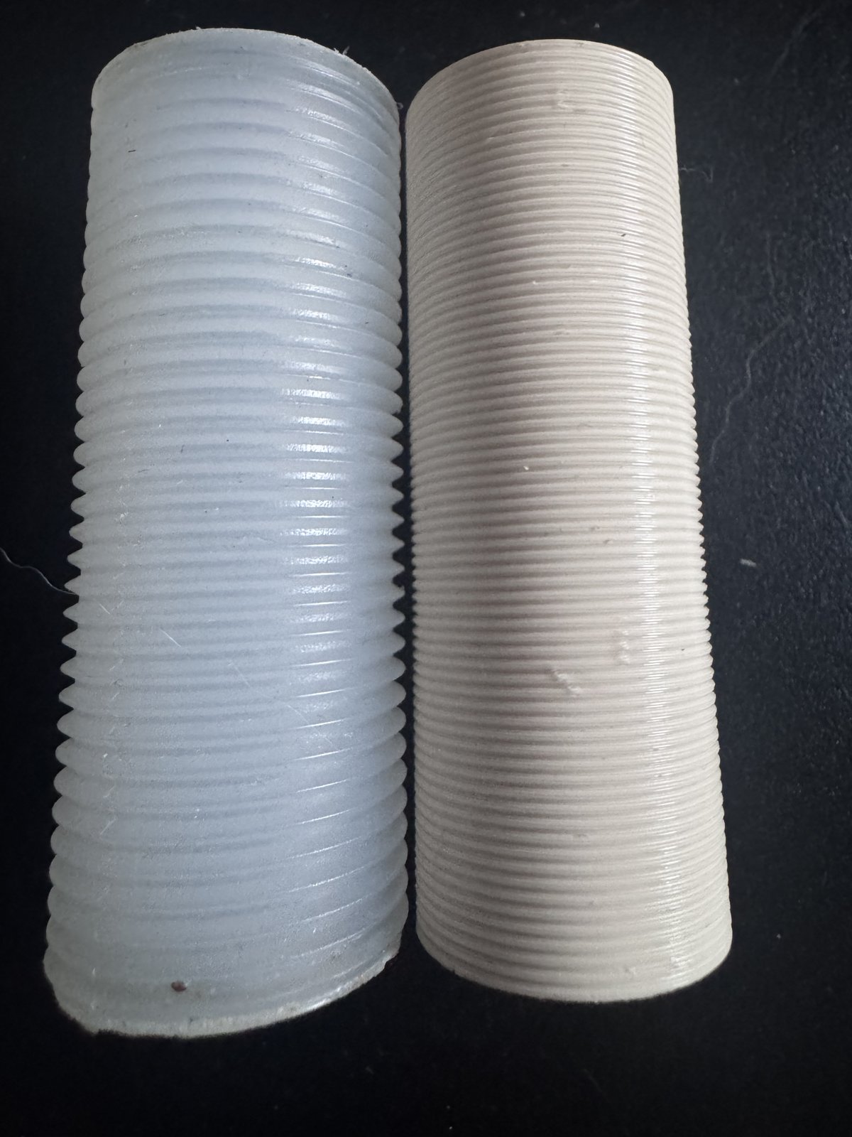
Iteration 2 (right) next to the original (left). Bigger now, but the threads still look like layer lines, not threads.
Iteration 2 came out closer in diameter. But the threads were still wrong. They didn’t look like threads — they looked like fine ribs. They felt like ribs. They wouldn’t engage anything.
Iteration 3: the pitch problem (and a moment of honesty)
I sent Claude a close-up of the original part next to the new print.
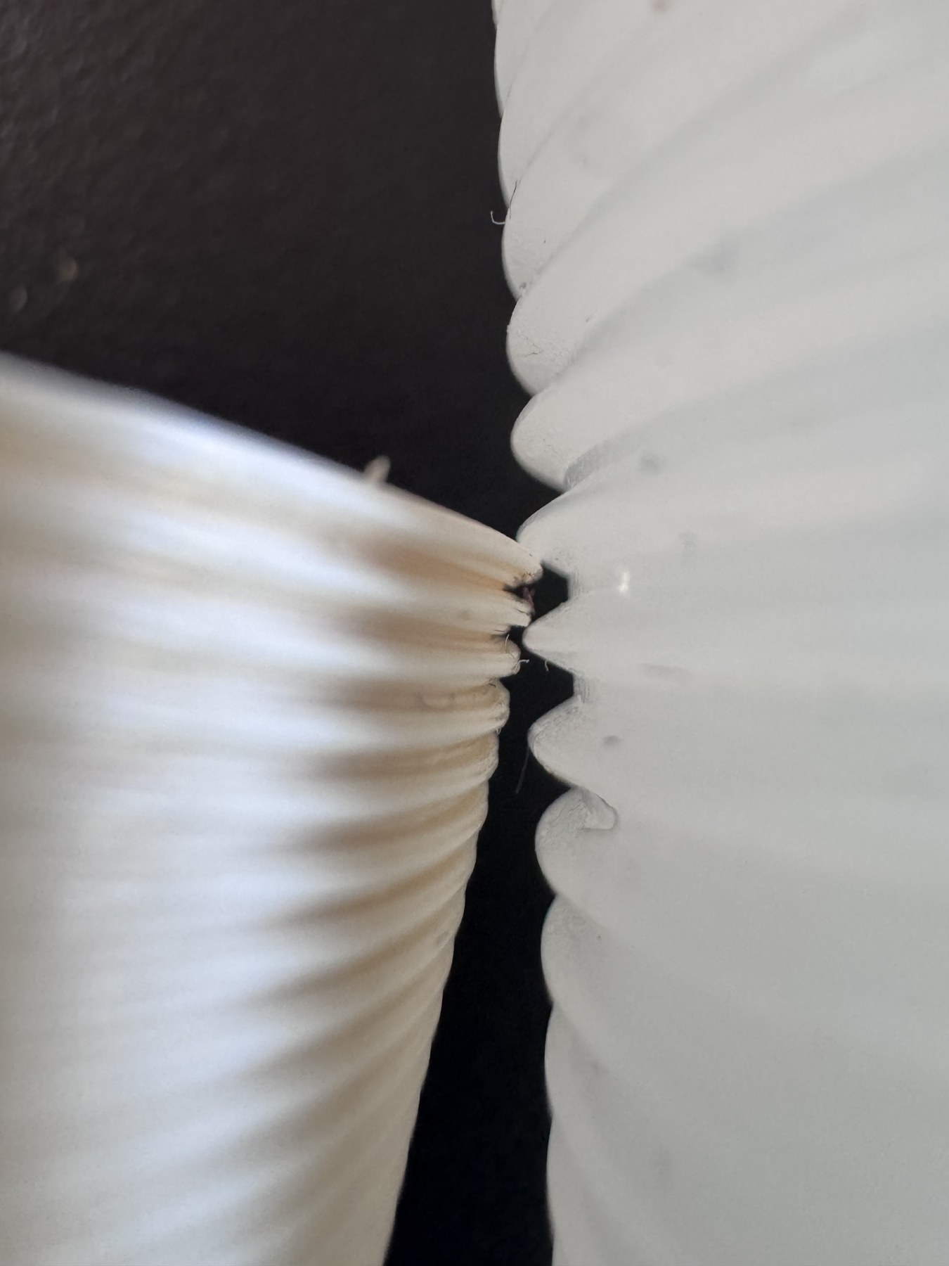
The aha moment. The original (right) has bold, deep V-grooves with a clear pitch. The print (left) has tiny dense ribbing. They are not the same kind of thread.
Claude looked at the photos and replied — and this was the part of the conversation I want to remember — “your initial measurement of ‘~1 mm between grooves’ was probably wrong. Looking at the photo, the original is more like 2 mm pitch.”
Then it asked me to take a ruler, lay it along the side of the original, and count how many ridges fit in 10 mm. Not “what do you think the pitch is” — count, with a ruler. Concrete instruction.
I counted. Five ridges in 10 mm. Pitch = 2.0 mm.
That single number changed everything. My first guess (1 mm pitch) had been off by 2x. At 2 mm pitch and 1.2 mm depth, with a 0.16 mm layer height, you get ~12 layers per thread cycle — that’s enough resolution for the printer to render an actual V-thread instead of an averaged ribbon.
Iteration 3 came out with the external thread looking exactly like the original. I screwed it into the dispenser body. It seated. It bottomed out at the right depth. External thread: perfect.
Iteration 3, external thread done right. PLA, 50% infill, 4 perimeters, ~30 minutes of print time.
Iteration 4: the wrong rabbit hole
I now made a small unforced error. I told Claude I’d measured the original’s “valley diameter” (the smaller diameter, between the threads) and it was 26.2 mm — which together with the 27.6 mm crest diameter means the actual thread depth is only 0.7 mm, not the 1.2 mm we were using.
Claude dutifully updated the model. Iteration 4 had shallower threads.
I never printed it. The reason: iteration 3 was already perfect. The 1.2 mm depth was theoretically more aggressive than the original’s 0.7 mm, but in practice the print’s threads matched the original’s because PLA loses dimensional accuracy at sharp peaks. The deeper “intended” thread compensated for the fact that the printer couldn’t actually render those peaks at full height anyway.
Lesson: when a thing fits, stop fitting it.
We reverted to v3 settings. Iteration 4 was abandoned.
Iteration 5: the bottle thread
The external thread was solved. The internal thread was a separate problem: it has to mate with the soap bottle, which has its own external thread. I’d been guessing at this thread’s specs, because the bottle wasn’t part of the broken piece — it lived in a different drawer.
Eventually I went and got it.
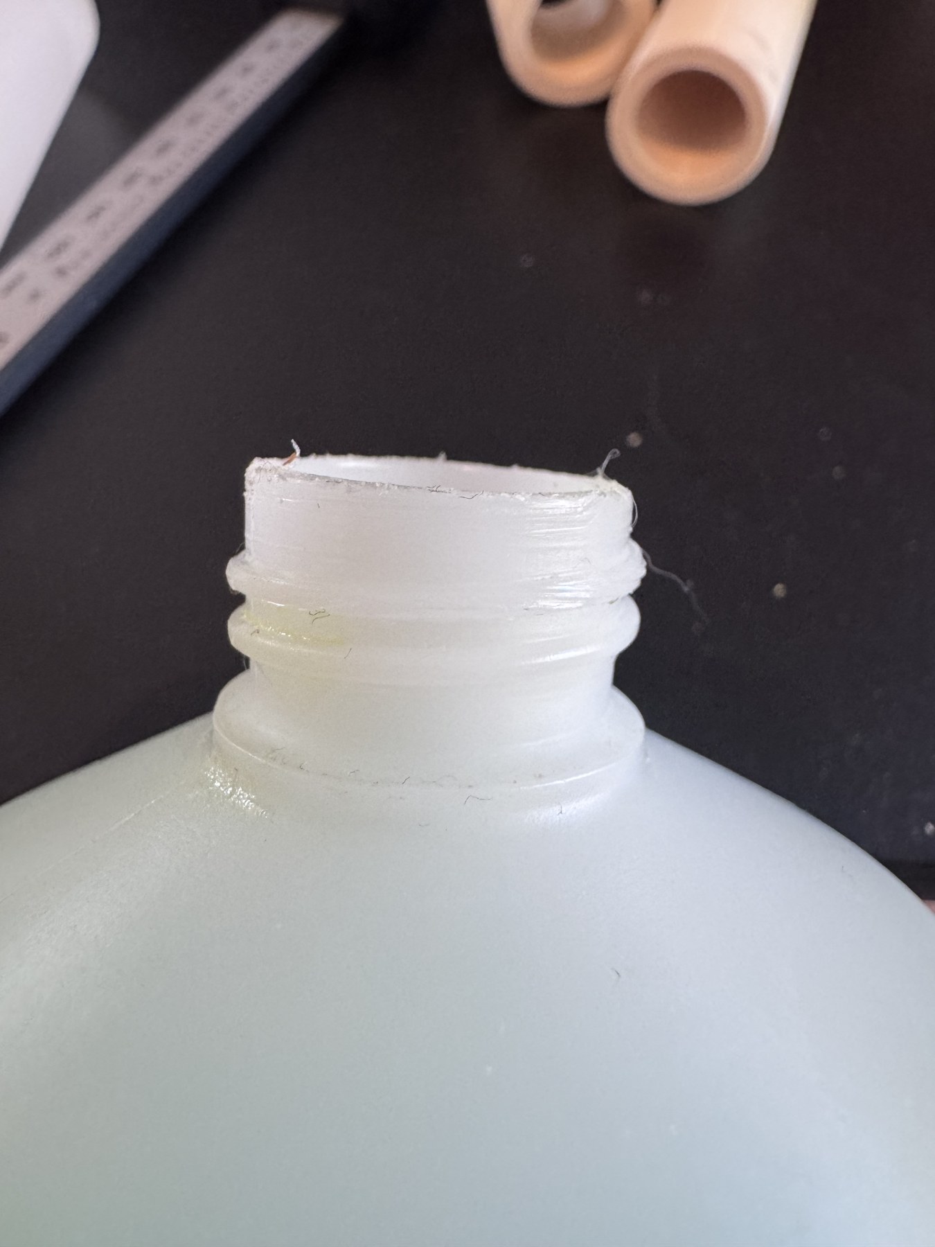
The bottle. Crest Ø22.2 mm, root Ø20.5 mm, neck height 14 mm, two ridges per 10 mm — pitch 5.0 mm. Way coarser than I’d assumed.
The bottle thread was pitch 5.0 mm — much coarser than the 1.5 mm I’d been guessing. This is why every internal thread we’d printed had been “OK if you really force it” — it wasn’t actually engaging the bottle’s threads, it was just rubbing past them.
We updated the internal thread parameters — pitch 5.0, minor diameter 20.5 + tolerance, major diameter 22.2 + tolerance. Iteration 5.
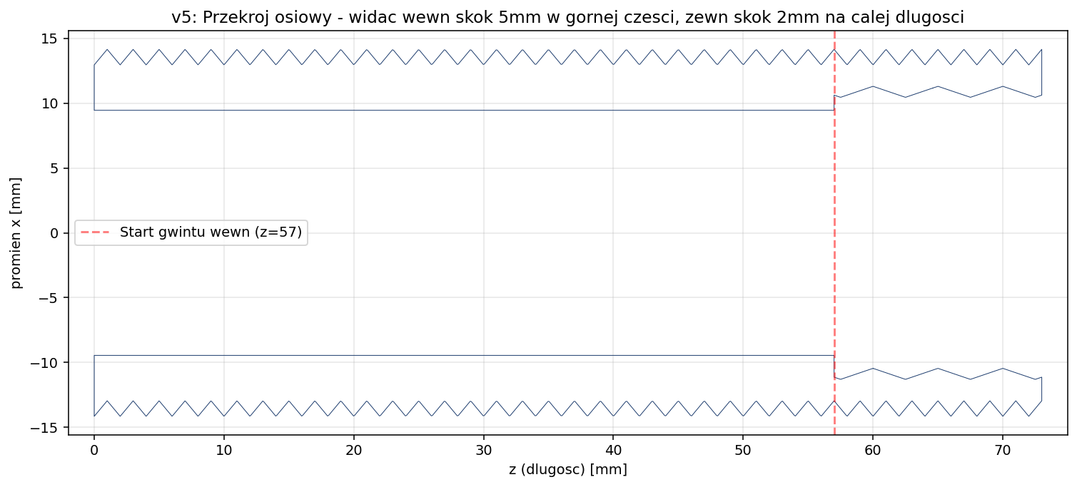
Cross-section of v5. External thread (dense zigzags, full length, 2 mm pitch). Internal thread (sparse zigzags, top 16 mm, 5 mm pitch). Smooth bore in between.
The bottle screws in smoothly. The dispenser body screws onto the column. The pump pushes soap. We are done.
What worked, what didn’t
What Claude did well:
- Asked the right questions before generating. This is huge. A lot of the value of working with a careful collaborator is that they make you specify what you actually want.
- Made the model parametric from the start. Every dimension was a named variable. When we changed pitch from 1.0 to 2.0, that was a one-line edit, not a re-modeling.
- Wrote both Python and OpenSCAD versions. The Python script could generate the STL directly without OpenSCAD installed; the SCAD file gave me a GUI editor for tweaking parameters with sliders.
- Computed PLA shrinkage compensation. When I told it “the print came out at 25.6 mm but should be 27.6 mm”, it correctly inferred that my printer loses 0.7 mm on outer diameters and applied that as a calibration constant for future iterations.
- Pushed back on my measurements. When I said “1 mm pitch”, it built that. When the result didn’t match the photo, it told me my measurement was probably wrong and asked me to recount with a ruler. This is exactly the right behavior — trust the user, but verify against ground truth.
Where Claude struggled (or where I had to step in):
- Cannot see what its model actually looks like in 3D. It generated 3D renders by rendering matplotlib triangle meshes, which is fine for cross-sections but doesn’t really show whether the threads “look right”. I had to print and photograph each version to give it visual feedback.
- Couldn’t measure the part itself. Every dimension came from me with a caliper. AI can’t reach into the world and measure things.
- Initial thread profile was sharp V instead of ISO truncated V. Fine for printing, slightly less accurate than a “real” thread library would produce. We also looked at switching to OpenSCAD with the BOSL2 library for proper ISO threads, but the simple V profile printed well enough that I never bothered.
- Got confused by my “valley diameter” measurement in iteration 4 and made a change that wasn’t needed. To be fair to it, the change was correct given the inputs — the issue was that the inputs were redundant and I should have known not to ask for the change in the first place.
The numbers
| Cost | Time | |
|---|---|---|
| Grohe official replacement (40535000) | ~€80 | + shipping |
| 3D-printed replacement | ~€0.50 of PLA | 5 iterations × ~30 min print = ~2.5 hours |
| AI CAD time | Cowork session | ~2 hours of back-and-forth |
The print cost is genuinely negligible. The total time investment, including the printing and measuring, was an afternoon. If I’d modeled this in Fusion 360 from scratch, it would have taken me longer — not because Fusion is slow, but because I’d have spent the first hour on a YouTube tutorial about modeling helical threads.
The interesting thing for me wasn’t the cost saving. It was the workflow. I never opened Fusion. I never wrote any CAD myself. I described a part, sent photos, took measurements when asked, and at the end I had a parametric model in Python and OpenSCAD that I can re-generate with new dimensions in 30 seconds.
What I’d do differently next time
- Take more measurements before starting. A single “outer diameter” is not enough. I should have measured: crest diameter, valley diameter, pitch (with a ruler, counted), thread length, internal bore diameter, internal thread crest, internal thread valley, internal thread pitch, internal thread length. Most of those I learned to measure during iterations 2–5 instead of iteration 0.
- Photograph the part next to a ruler so the AI has a scale reference. I never did this and it would have eliminated a couple of round trips.
- Print a small thread-only test piece first. A 20 mm tall stub with the same external thread profile. Test it against the dispenser body before committing to a full 73 mm print. Saves filament, saves time.
The model
I uploaded the final part to MakerWorld so anyone else with a snapped Grohe Cosmopolitan column can print one. It’s parametric, BSD-style license. If you measure your own broken part and the dimensions are different, the OpenSCAD source has all the parameters at the top — change them, hit F6, export STL.
Grohe Cosmopolitan 40535000 — Column Spare Part on MakerWorld
The total saved: ~€79.50. The lesson learned: AI is genuinely useful for the kind of CAD work where the geometry is straightforward but tedious, and where you’d rather describe a part than draw it. It is not yet useful for the parts where the geometry is the hard part — designing a new mechanism, choosing tolerances by feel, optimizing for a specific manufacturing process. But for “make me a copy of this broken thing”, it’s a quiet revolution.
The fact that I was sitting at my dining table calling out caliper measurements while a chatbot wrote helical thread mesh code in Python is the kind of thing that, ten years ago, would have sounded like science fiction. Today it just sounds like — Tuesday.
If you’ve done something similar — repaired a household item with AI-assisted CAD — I’d love to see it. Drop me a line.
A note on style: English isn’t my first language. I drafted this post myself based on the work I did, then used an AI assistant to help with formatting and copy-editing. The technical content, decisions, numbers, and lessons are entirely mine.
Also — speaking of “how much did this actually cost?”: I built a small side project called Cost Slicer that estimates the real cost of a 3D print (filament + electricity + machine time) from a sliced G-code file. If you’re curious whether printing your own part is actually cheaper than buying it, give it a try.